RK0020VOARD0003Q11G

Pneumatic actuators - RACKON - Rack & Pinion pneumatic actuators RK20 F03/F05 11 Basetta Namur GAS

RACKON - Double acting DA RK0020VOARD0003Q11G
Size:RK20
ISO:F03/F05
Star Shaft:11
Air Connection:Basetta Namur GAS
116,50 €Excl. VAT
list price
Qty
add
to cart
Article Weight [kg]
RK0020VOARD0003Q11G 1.40
GENERAL INFO
RACKON - Double acting DA
  • benefits
  • features
  • dimensions
  • materials
  • diagrams and breakaway torque
  • specifications
  • documents

RACK & PINION KINEMATICS

DOUBLE ADJUSTMENT

DA DOUBLE ACTING

SR SPRING RETURN

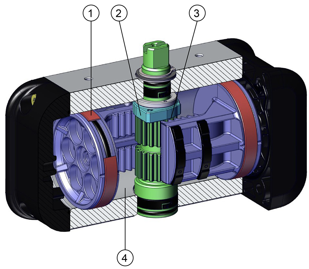
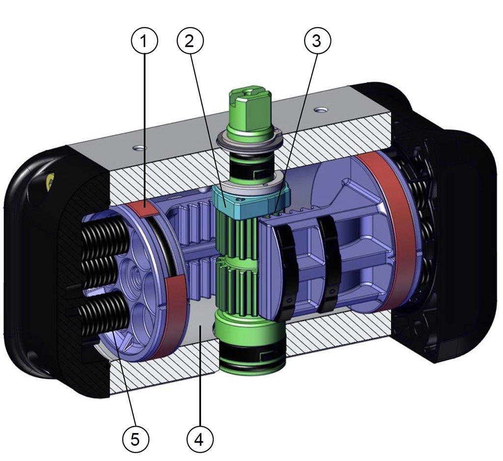
1. Energized and self-lubricated strips.

Less friction between piston and cylinder.

It prevents the bonding of the seal to the cylinder even after long periods of inactivity.


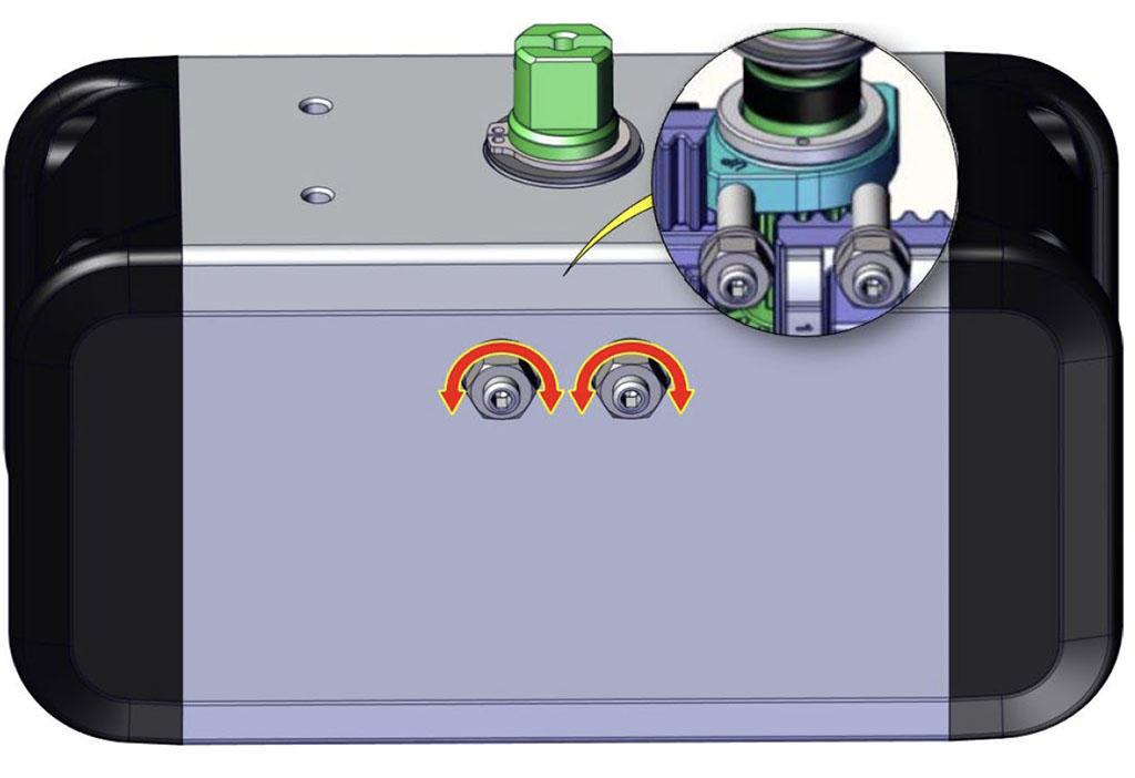
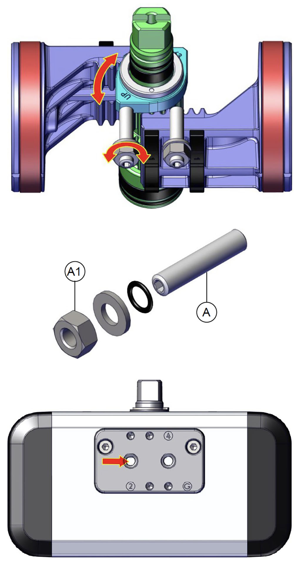
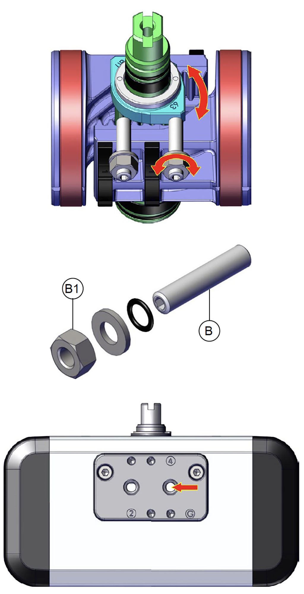
2. Adjustment cam made by steel.

Possibility to adjust the closing and/or opening with a standard actuator (± 5° for each adjustment).

Simplicity and reliability of adjustment.


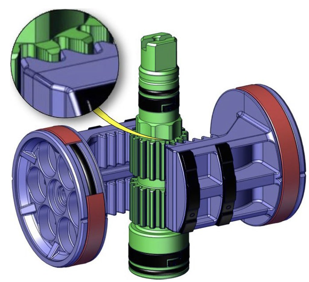
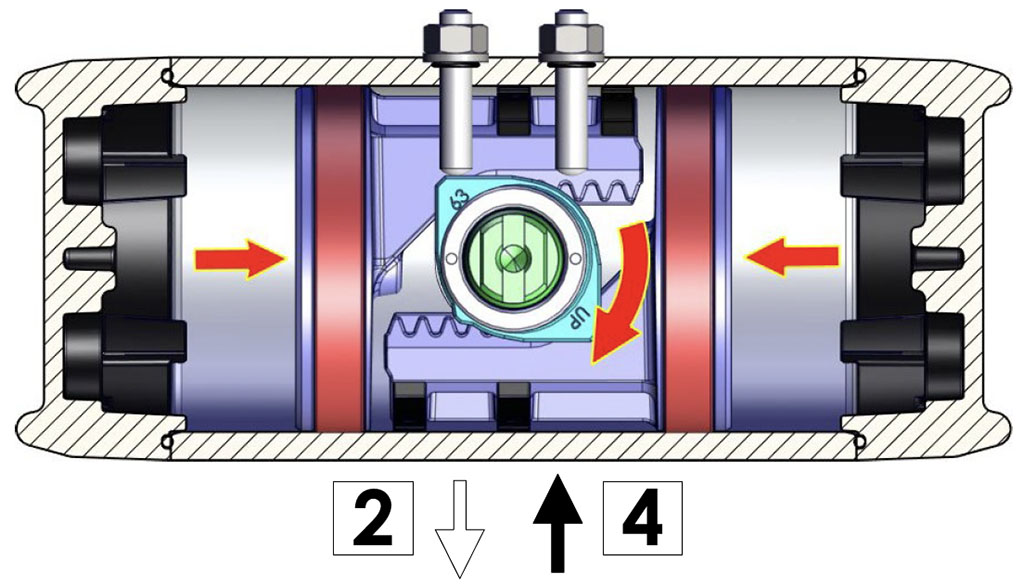
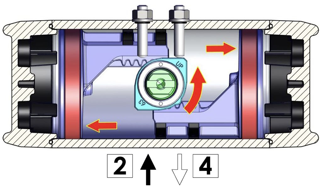
3. Transformation of linear motion into rotary motion using Rack and Pinion kinematics.

Linear torque (BTO & BTC), suitable for ball valves.

High adjustment precision thanks to the rigidity of the rack and pinion system and the mechanical stop between cam and adjustment grub screw.

Uniform rotation speed.


4. Rolled cylinder.

Less wear of the energized ties thanks to the low roughness of the surface (0.15 μm Ra).


5. Cartridge spring modular system.

High configuration flexibility and precision of the torque generated by the springs.

High range of configurations.


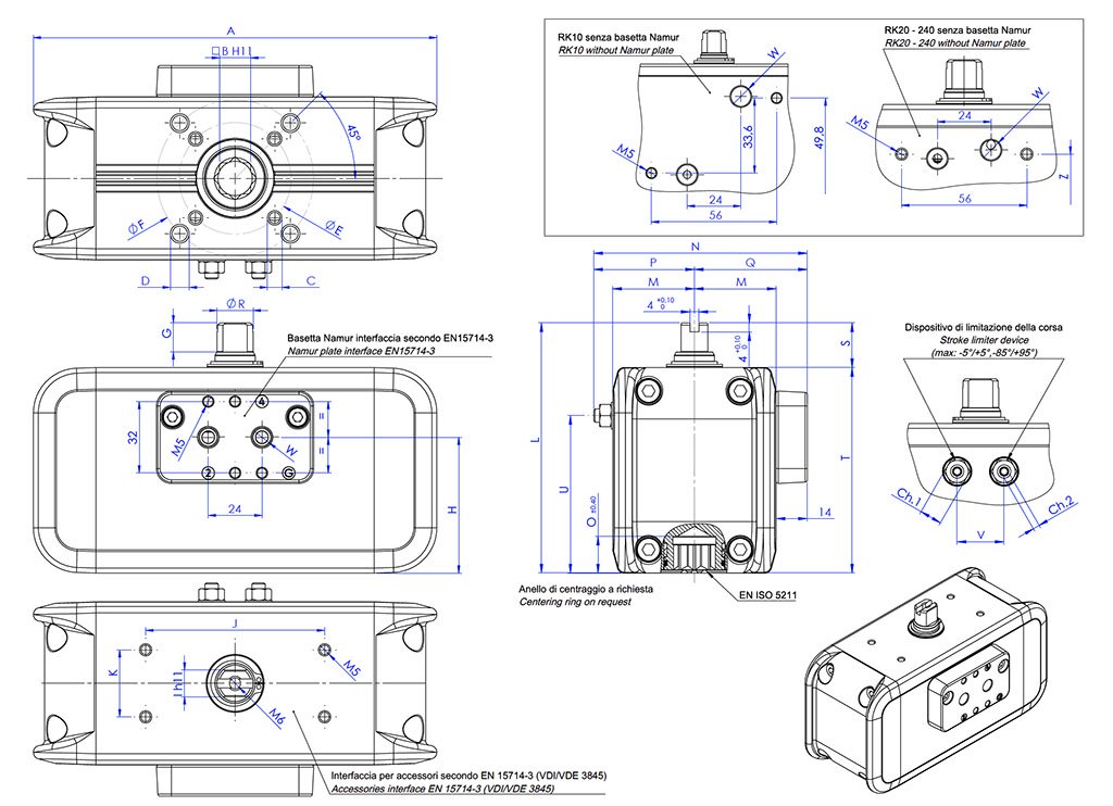
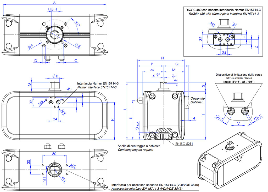
NAMUR interface for solenoid valves can be available on complete range.

With plate reported from RK10 to RK240. - Integrated for RK 300 and RK480.


NPT air hole threads available on request.

With plate reported for all sizes.


100% in- house manufacturing process technology.

Maximum control and accuracy in all the stages of the manufacturing process.


ATEX compliance.

Installation is allowed in a potential explosive environment.


Up to SIL 3 Certified.

Guarantee of the high level of functional safety.

TECHNICAL FEATURES
• Torque from 10 Nm to 474 Nm.
• Mounting flange according to EN ISO 5211: F03 - F04 - F05 - F07 - F10 - F12.
• In accordance with EN 15714-3.
• In conformity with directive ATEX 2014/34/EU.
• Rotation angle: 100° (-5°, +95°).
• Double adjusting +5° and -5° for each end position (0° and 90°).
• Torque: directly proportional to the air supply (see table).
• The code numbers after the RK letters, always correspond to the torque in Nm by 5,6 bar air supply.

WORKING CONDITIONS
• Standard temperature range: -20°C +80°C.
    Special versions:
    - high temperature: -20°C +150°C.
    - low temperature: -50°C +60°C.
• Nominal pressure: 5.5 bar; maximum operating pressure 8 bar.
• Operating medium: filtered compressed air, no lubrication needed according to UNI EN 15714-3:2009.
• In case of lubrication, use non-detergent oil, compatible with the internal seals.

SPECIAL VERSION ON REQUEST, CODING KEY


CHARACTERISTIC
Actuator Type
RK
Size
0010, 0020, 0040, 0060, 0080, 00120, 00160, 0240, 0300, 0480
Customer
VOOMAL
Rotation Angle [°]
A90°
B*180°
C*120°
D*135°
Rotation direction
RClockwise rotation
LCounter-clockwise rotation
Functioning configuration
SSpring Return N.C.
OSpring Return N.O.
DDouble Acting
Springs
00No springs
20Springs 2,0 bar
25Springs 2,5 bar
30Springs 3,0 bar
35Springs 3,5 bar
40Springs 4,0 bar
45Springs 4,5 bar
50Springs 5,0 bar
55Springs 5,5 bar
60Springs 6,0 bar
Flange or smaller flange in case
of double flange available
03F03
04F04
05F05
07F07
10F10
12F12
Shaft shape
QStar shaft
D*Flat head shaft
Shaft dimension
09Shaft dimension 9 mm
11Shaft dimension 11 mm
14Shaft dimension 14 mm
17Shaft dimension 17 mm
22Shaft dimension 22 mm
27Shaft dimension 27 mm
Air connection
GNamur plate GAS
NNamur plate NPT
0Gas Thread on the cilynder
(no Namur interface)
INamur interface, integrated Gas threads
Version
-Standard
6*Low temperature
4*High temperature

* Only on request.
N.B. For special versions contact OMAL.


CODING EXAMPLE FOR RACKON

Product Code: RK0040VOARD0005Q11G
Product description: RACKON 40 PNEUMATIC ACTUATOR DOUBLE ACTING ISO F05 07 STAR SHAFT 11mm WITH GAS NAMUR PLATE.

Product Code: RK0300VOARD0007Q22I
Product description: RACKON 300 PNEUMATIC ACTUATOR DOUBLE ACTING ISO F07 10 STAR SHAFT 22mm NAMUR GAS INTERFACE INTEGRATED ON BODY.

Product CodeRK0040VOARS6005Q11G
Product description: RACKON 40 PNEUMATIC ACTUATOR SPRING RETURN 6BAR ISO F05 07 STAR SHAFT 11mm WITH GAS NAMUR PLATE.

Product Code: RK0300VOARS6007Q22I
Product description: RACKON 300 PNEUMATIC ACTUATOR SPRING RETURN 6BAR ISO F07 10 STAR SHAFT 22mm NAMUR GAS INTERFACE INTEGRATED ON BODY.

RK10 ÷ RK240

DIMENSIONS [mm]
Size
RK10RK10RK20RK20RK20RK20RK40RK40RK40RK40RK60RK80RK120RK160RK240
ISOF03F04F03/F05F03/F05F04F04F04F04F05/F07F05/F07F05/F07
F05/F07
F05/F07
F07/F10F07/F10
A121,7
121,7
153,7
153,7
153,7
153,7
180,4
180,4
180,4
180,4
215,4
235,5
265,9
285,9
318,4
B9
9
911911
11
14
11
141417172222
C x depthM5x8
M5x8
M5x8
M5x8
M5x8
M5x8
M5x8
M5x8
M6x9
M6x9
M6x9
M6x9
M6x9
M8x12
M8x12
D x depth--M6x9
M6x9
----M8x12
M8x12
M8x12
M8x12
M8x12M10x15
M10x15
E36
4236
36
4242424250
50
50
50
50
7070
F--5050----70
70
70
70
70
102102
G101010101010
1313
13
13
13
13
13
13
19,5
H333350,950,950,9
50,9
60,8
60,8
60,8
60,8
68,7
75,6
87,6
97,5
112
I999999
12
12
12
12
12
15151922
J505080808080
80
80
80
80
80
80
80
80
80
K252530303030
30
30
30
30
30
30
30
30
30
L8080100100100100
112
112
112
112
122
130143154180
M24,524,530303030
36,5
36,5
36,5
36,5
41,5
46
51
56,5
64
N71*
71*
82,5*
82,5*
82,5*82,5*
95,5*
95,5*
95,5*
95,5*
107,8*
116,5*
127*
141*
159*
O10,7
10,7
13,213,2
13,2
13,2
16,5
16,5
16,5
16,5
16,5
19,3
19,3
24,3
24,3
P32,5*
32,5*
38,5*38,5*
38,5*
38,5*
45*
45*
45*
45*
52,3*
56,5*
62*
70,5*
81*
Q38,5
38,5
4444
44
44
50,5
50,5
50,5
50,5
55,5606570,578
R10,9
10,9
12,712,7
12,7
12,7
16,2
16,2
16,2
16,2
1820,222,525,531,8
S15
152020
20
20
20
20
20
20
20
20
20
20
30
T65658080
80
80
92
92
92
92102110123134150
U494959,7559,75
59,75
59,75
70,5
70,5
70,5
70,5
70,5
8697,75106,25120,5
V16161919
19
19
21
21
21
212426323641
W standard (GAS)1/8"
1/8"
1/8"
1/8"
1/8"
1/8"
1/8"
1/8"
1/8"
1/8"
1/8"
1/8"
1/4"
1/4"
1/4"
W special (NPT)1/8"-27
1/8"-27
1/8"-27
1/8"-27
1/8"-27
1/8"-27
1/8"-27
1/8"-27
1/8"-27
1/8"-27
1/8"-27
1/8"-27
1/4"-18
1/4"-18
1/4"-18
Ch.11010101010
1010
1010
10
1313131618
Ch.23333333
33344456
Weight (kg)0,90,91,41,41,41,42,1
2,12,12,1
2,93,75,16,59
Air (dm3/cycle)0,120,120,250,250,250,250,48
0,480,48
0,48
0,75
1,04
1,481,99
2,91
Z49,849,8
59,959,959,959,969,8
69,869,8
69,8
77,7
84,6
96,6
106,6
121
W1/8"
1/8"
1/8"
1/8"
1/8"
1/8"
1/8"
1/8"
1/8"
1/8"
1/8"
1/8"
1/4"
1/4"
1/4"

H = CENTER OF PLATE'S FIXING.
* Variable according to adjustment.

RK300 ÷ RK480

DIMENSIONS [mm]
SizeRK300RK480
ISOF07/F10
F10/F12
A352,4
393,4
B22
27
C x depthM8x12
M10x15
D x depthM10x15
M12x18
E70
102
F102
125
G19,5
19,5
H125
145
I2227
L192214
M69,580
N156,5*180*
O24,329,5
P87*100*
Q83,594
R31,838
S3030
T162184
U131149,5
V4652
W standard (GAS)1/4"1/4"
W special (NPT)1/4"-18
1/4"-18
Ch.11821
Ch.266
Weight (kg)11,416,3
Air (dm3/cycle)3,775,8
Z124,5144,5
W1/4"
1/4"


H = CENTER OF PLATE'S FIXING.

* Variable according to adjustment.

RK10 ÷ RK480

MATERIALS
Pos.
DescriptionQ.ty
Material
1Cylinder
1Aluminium alloy
2Shaft
1Steel alloy
3*Slide ring (upper shaft support)
1Acetalic resins
4*Slide ring (lower shaft support)
1Acetalic resins
5*O-Ring (lower shaft sealing)
1Nitrilic rubber
6Cam
1Steel alloy
7*Internal support ring
1Acetalic resins
8*External support ring
1Acetalic resins
9Washer
1Stainless steel
10*Seeger
1Stainless steel
11*O-ring**
2Nitrilic rubber
12*O-ring (upper sealing shaft)
1Nitrilic rubber
13Namur plate**
1Aluminium alloy
14Screws**
2Stainless steel
15*O-ring
2Nitrilic rubber
16*Washer (limit stroke)
2Stainless steel
17*Hexagon nut (limit stroke)
2Stainless steel
18*Grub screw (limit stroke)
2Stainless steel
19Piston
2Aluminium alloy
20*Piston support leg
4Acetalic resins
21*Dynamic seal
2Polyurethan
22*O-ring
2Nitrilic rubber
23*End-cap O-ring
2Nitrilic rubber
24Cap
2Aluminium alloy
25Screws
8Stainless steel

* Components of spare part kit.
** Not present for some models, see code table.

"DA" OUTPUT TORQUE DIAGRAM (Nm)

RACKON "DA" OUTPUT TORQUE TABLE (Nm)
SizeAir bar
2 bar2,5 bar3 bar3,5 bar4 bar4,5 bar5 bar5,5 bar5,6 bar6 bar7 bar8 bar
RK103,74,75,66,67,58,49,410,310,511,213,115,0
RK207,39,111,012,814,616,418,320,120,521,925,629,2
RK4013,917,420,924,427,931,334,838,339,041,848,755,7
RK60
21,226,531,937,242,547,853,158,459,563,774,384,9
RK80
30,037,544,952,459,967,474,982,483,989,9104,9119,9
RK120
42,753,464,074,785,496,1106,7117,4119,5128,1149,4170,8
RK160
58,573,287,8102,5117,1131,7146,4161,0163,9175,6204,9234,2
RK240
85,2106,5127,8149,1170,4191,7213,0234,3238,6255,6298,2340,8
RK300
109,8137,2164,7192,1219,6247,0274,5301,9307,4329,3384,2439,1
RK480
172,4215,5258,5301,6344,7387,8430,9474,0482,6517,1603,3689,5

For output torque at different pressures contact OMAL.

DOUBLE ACTING ACTUATOR WORKING PLANE

WORKING PLANE
Supplying air through the air connection 4, the pistons move towards the center and shaft rotate in a clockwise direction.
The above drawing shows the final position.

WORKING PLANE
Supplying air through the air connection 2, the pistons move outwards the center and shaft rotate in a counter-clockwise direction.
The above drawing shows the final position.

INSTRUCTIONS FOR ADJUSTING THE STROKE OF THE DOUBLE ACTING ACTUATOR

OPENING ADJUSTMENT

CLOSING ADJUSTMENT

A) Check that there is no pressurized air in the actuator (in both chambers).
B) Loosen locknut A1.
C) Supply air to hole “2” (sufficient only for movement) the pistons will be in the end of stroke.
D) Screw or unscrew the screw A with an Allen key for the desired adjustment (maximum adjustment range ± 5°).
E) Once the adjustment has been made, with an Allen key stop the screw A, at the same time with a wrench tighten the locknut A1.

N.B. If necessary, repeat the operations until the desired setting is obtained.

A) Check that there is no pressurized air in the actuator (in both chambers).
B) Loosen locknut B1.
C) Supply air to hole “4” (sufficient only for movement) the pistons will be in the end of stroke.
D) Screw or unscrew the screw B with an Allen key for the desired adjustment (maximum adjustment range ± 5°).
E) Once the adjustment has been made, with an Allen key stop the screw B, at the same time with a wrench tighten the locknut B1.

N.B. If necessary, repeat the operations until the desired setting is obtained.

disponibilita
SHIPPING WITHIN
48 HOURS

spedizioni
FAST DELIVERY
FROM € 7,00
mondo
DELIVERY
WORLDWIDE