REGISTRATION/LOGIN
Enter your login details to access more info on OMAL valves and actuators
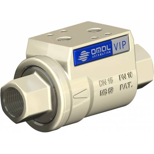
| Article | Nominal pressure | Weight [kg] | Variant | Spare part kit |
|---|---|---|---|---|
| VDA20009 | PN 10 | 5.5 | Ottone | KGVV0109 |